About the Project
This project was developed within the scope of Applied Microwave Engineering course at Istanbul Medipol University. The goal is to design a receiver/transmitter (RX/TX) microstrip patch antenna pair operating at 1575 MHz (GPS L1 Band) on a single FR-4 substrate.
The design was simulated and optimized using CST Studio Suite. The antennas are optimized for production with an LPKF machine to reduce costs and facilitate integration.
Technical Specifications
- Operating Frequency: 1575 MHz
- Substrate: FR-4 (Dielectric Constant: 4.3, Thickness: 1.6mm)
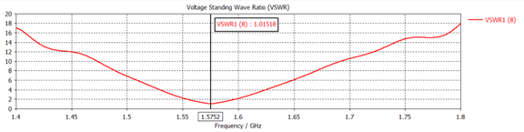
- Bandwidth: ≥ %2
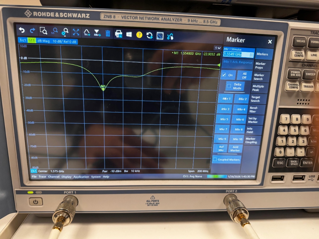
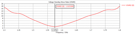
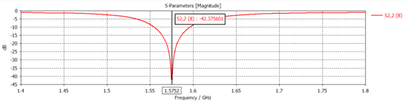
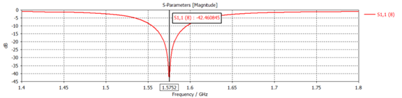
- Return Loss (S11): -45.375 dB (Perfect match at 1.5752 GHz)
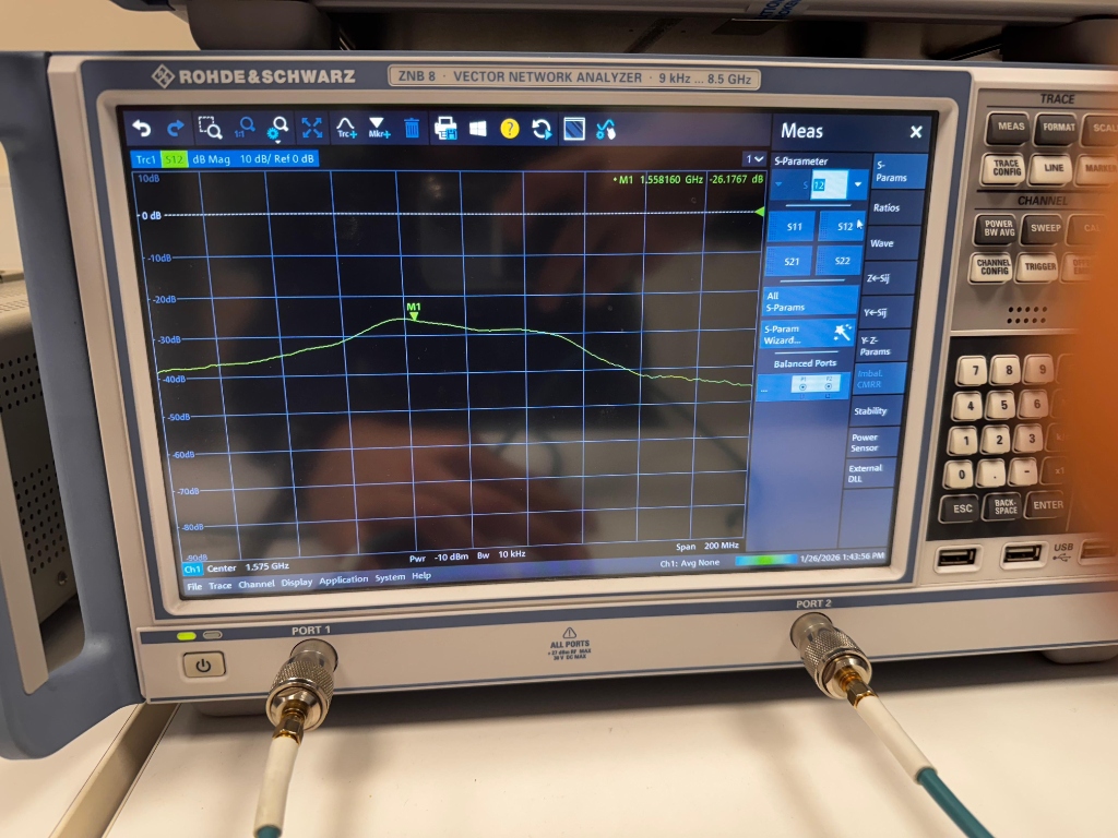
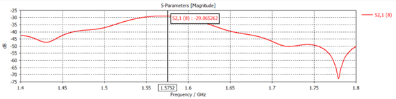
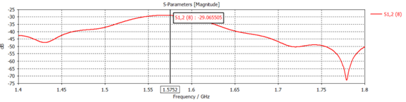
- Isolation (S21): -29.06 dB (Prevents signal interference)
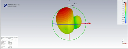
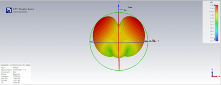
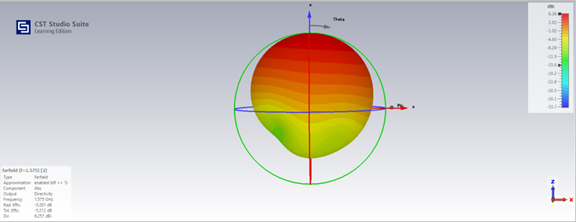
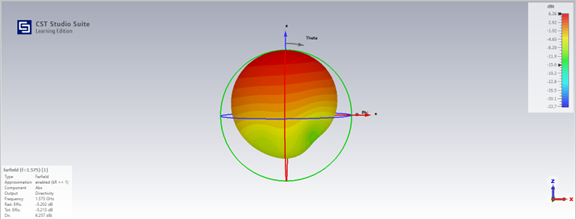
- Directivity: 6.255 dBi
- Feeding Method: Quarter-Wave Transformer with 50Ω line
Design and Simulation Process
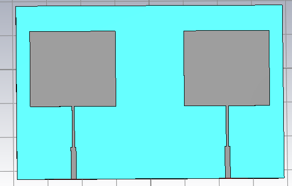
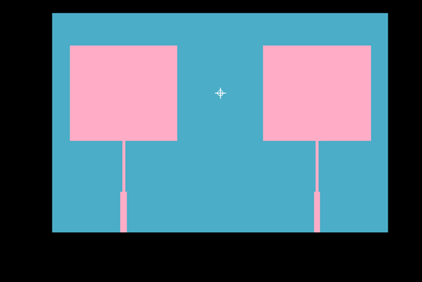
Antenna dimensions were determined by theoretical calculations and optimized in the simulation environment. The patch width is calculated as approx. 50mm and length as 44.38mm. A quarter-wave transformer is placed between the feed line and the antenna for impedance matching.
Fabrication and Measurement Results
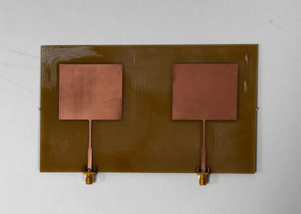
The antenna design was successfully fabricated on an FR-4 substrate using the LPKF ProtoMat device and tested with the Rohde & Schwarz ZNB 8 Vector Network Analyzer (VNA).
Simulation vs. Real Measurement
The table below provides a comparison between the manufacturing results (VNA) and the CST Studio simulation data:
| Parameter | Simulation (CST) | Measurement (VNA) | Diff / Comment |
|---|---|---|---|
| Resonance Frequency | 1.5752 GHz | 1.5549 GHz | ~1.3% shift (Acceptable) |
| S11 (Return Loss) | -45.38 dB | -22.90 dB | Great match (below -10dB is good) |
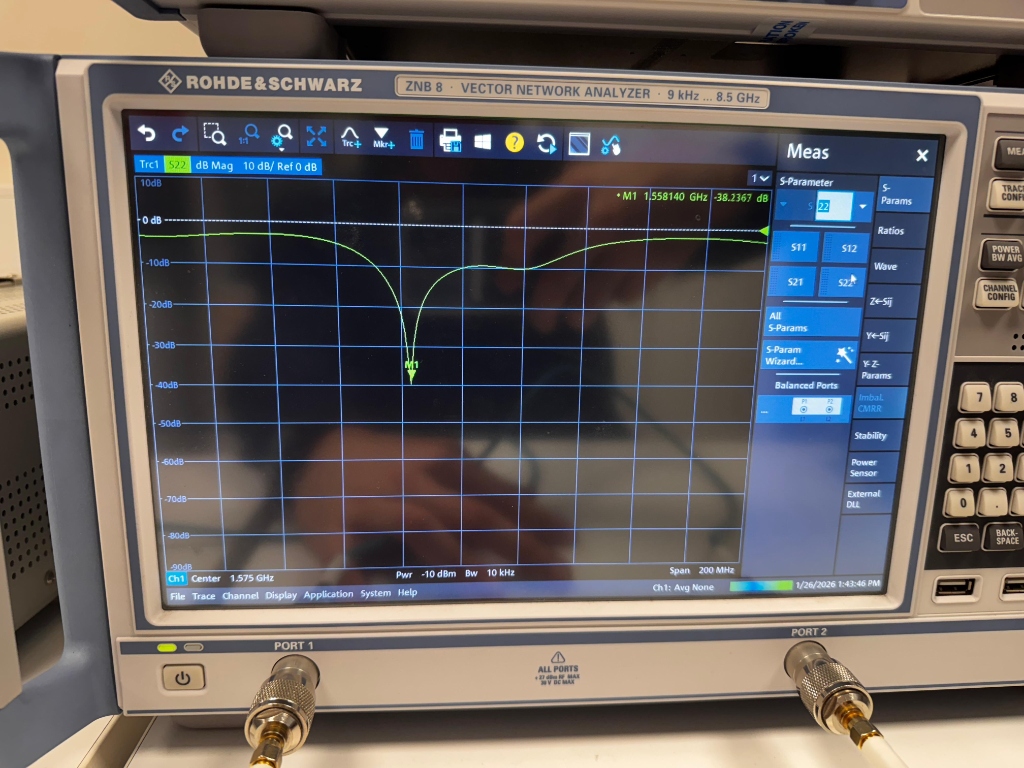
| S22 (Return Loss) | (Symmetrical) | -38.23 dB | Excellent match |
| S12 (Isolation) | -29.06 dB | -26.17 dB | High isolation maintained |
*The frequency shift is primarily due to slight variations in the FR-4 dielectric constant (epsilon_r) and manufacturing tolerances. However, with -22dB return loss, the antenna operates with very high performance.
VNA Measurement Screens